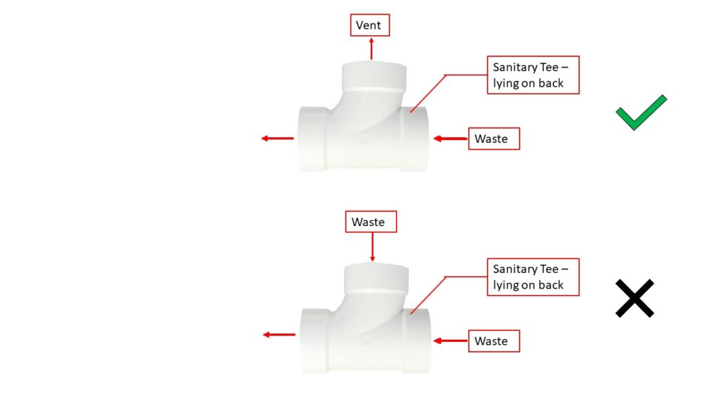
Incorrect use of sanitary tees in drainage systems is a common problem. What is their proper use in plumbing DWV piping? Table 706.3 of the IPC provides code requirements for the proper use of these plumbing fittings.
[Read more…]Incorrect use of sanitary tees in drainage systems is a common problem. What is their proper use in plumbing DWV piping? Table 706.3 of the IPC provides code requirements for the proper use of these plumbing fittings.
[Read more…]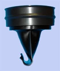
Trap seal devices must be prevented from losing their water seal. Loss of the water seal allows sewer gas to enter the building.
The International Plumbing Code (IPC)Section 1002.3, 2018 edition, discusses the types of prohibited traps. Specifically, the first prohibited type of trap is “Traps that depend on moving parts to maintain the seal.” Some interpret this language to prohibit the use of trap seals.
The Code Commentary states that “a trap is intended to be a simple U-shaped piping arrangement that offers minimal resistance to flow. Prohibited traps do not have a simple U-shaped design or configuration.” A P-trap with a trap seal still has the simple U-shaped design or configuration. Regarding this first prohibition, the Code Commentary states, “Item 1 refers to mechanical traps that use moving parts such as floats or flappers.”
Note that this code language is in reference to traps, not trap seals.
[Read more…]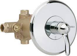
Showers pose a risk of scalding from hot water. In addition to the risk of hot-water scalding, thermal shock from rapid changes in shower water temperature can cause slips and falls.
To protect the user, plumbing codes require that water delivered from showers not exceed 120°F. The plumbing codes no longer consider water heater thermostats, by themselves, a safe means of controlling water temperatures. They require an ASSE 1016 shower valve to control the maximum water temperature and to prevent scalding and thermal shock.
ASSE 1016 contains requirements for three different types of shower valves.
Design engineers must decide which type of ASSE 1016 shower valve to specify. First, for individual showers and tub/showers, a Type P pressure-compensating valve prevents thermal shock. Unless thermal shock protection is provided by another device, such as an ASSE 1066 pressure-compensating device, the plumbing code requires an ASSE 1016 Type P or Type P/T shower valve.
Second, the question becomes, is the additional thermostatic protection provided by a Type P/T shower valve needed? This often depends on the hot water system and the expected temperature variation at the shower fixture. Some hot water systems have large temperature variations, for example, residential storage-type water heaters with no recirculation. Due to the phenomenon of “thermal stacking,” hot water temperatures in these systems can easily vary by as much as 10 – 15 degrees F. Another consideration is whether the facility is at a higher risk of scalding, such as hospitals, nursing homes, and assisted living centers. In these instances, a Type P/T shower valve is a good idea.
By contrast, some commercial hot water systems with master mixing valves, continuous recirculation, and/or precise controls may have nearly constant hot water temperatures at the shower fixtures. For these systems, a Type P shower valve may be sufficient to limit the shower temperature to 120°F.
Here is a conservative approach: if system temperatures are unstable or unknown, install a thermostatic device (ASSE 1017 master mixing valve in conjunction with ASSE 1016 Type P shower valves, or ASSE Type P/T shower valves, etc.) at some point between the water-heating source and the delivery point. Although this is not a code requirement, maintaining a maximum temperature of 120°F is. A thermostatic device will greatly reduce temperature swings in the hot water system and protect the end-user in the event of a water heater thermostat failure. Design engineers should evaluate the hot water system and make an informed decision about scald protection. Specifying what “everyone else does” or “what meets the code” may not provide the required level of safety needed to prevent scalding.
Given the allowable temperature variation in an ASSE 1016 shower valve, at what discharge temperature should the installer set the shower valve to ensure a maximum water temperature of 120°F? Outlet temperatures for ASSE 1016 valves can vary by +/- 3.6 degrees when tested at 45 psi. At higher operating pressures, the temperature swing could exceed ±3.6°F. Therefore, I recommend setting the high-limit stops on shower valves to provide a discharge temperature of 110 degrees F. A shower valve adjusted to provide a 110 degrees F discharge may vary from 105 to 115 degrees F. This temperature range provides a comfortable shower without the risk of scalding from hot water.
Options: integral check stops: Always specify shower valves with integral check stops to prevent the hot water from crossing over into the cold water piping.
The plumbing specifications should require high-limit temperature stops in the shower valves to be set at the time of installation. The design engineer should also check the hot water temperatures at the shower discharge during site inspections prior to project completion.

The IFGC lists six exceptions for the requirement of paragraph 303.3. These six exceptions allow gas appliances in these prohibited locations when specific conditions are met. [Read more…]
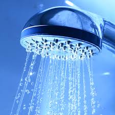
Currently, standard shower valves and showerheads have a minimum flow rate of 2.5 GPM. Water-saving shower valves and showerheads are available with lower flow rates. WaterSense showerheads are rated at 2.0 GPM. There are also showerheads available that have 1.5, 1.0, and even 0.5 GPM flow rates. These various options for minimum flow rates in shower valves and showerheads create opportunities for misapplication and dangerous outcomes.
When the flow rate of a showerhead is less than the minimum flow rate of the corresponding shower valve, the potential for scalding increases for the following reasons: [Read more…]

Roger W. Griffith, P.E., was appointed to the International Code Council’s Plumbing/Mechanical/Fuel Gas Code Action Committee (ICC PMGCAC) for the 2018-2019 code development cycle.
The ICC PMGCAC is responsible for reviewing and proposing revisions to the International Plumbing Code, International Mechanical Code, International Fuel Gas Code, International Private Sewage Disposal Code, International Swimming Pool and Spa Code, and the mechanical, plumbing, and fuel gas chapters of the International Residential Code. These codes govern how mechanical, plumbing, and fuel gas systems must be designed and installed to protect the health, safety, and welfare of the public.
Appointment to the ICC PMGCAC is by selection — members are chosen based on their technical expertise and professional standing in the industry. Committee members review proposed code changes, evaluate technical evidence, and vote on revisions that become adopted into the next code edition.
Mr. Griffith’s participation in national code development directly informs his expert witness practice. His firsthand understanding of how code language is developed, debated, and interpreted gives him unique insight into the intent behind code requirements — insight that is directly applicable in litigation involving alleged code violations and system failures.

When designing mechanical systems, engineers and designers often need help specifying the type and thickness of insulation for ducts and piping. Good resources are always valuable and welcome when time constraints leave little time for insulation specifications.
The National Insulation Association’s (NIA) new redesigned website is a helpful resource for all things insulation, from training, design help, and specifications. Check out their new website and bookmark it for return trips. Enjoy!
For suggestions on future blog posts, make a suggestion.

The recent outbreak of Legionnaires’ disease in New York City has brought renewed attention to the inherent risks posed by Legionella bacteria in HVAC and plumbing systems. There are several things that plumbing engineers and designers can do to minimize the risk of legionella colonizing and growing in plumbing systems.
[Read more…]Selection and Installation of Thermal Expansion Tanks
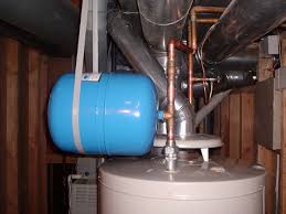
See Part 2 for the calculation of the expansion tank volumes. Now, using the calculated acceptance volume and the tank’s total volume, select an expansion tank from the manufacturer’s data that meets these requirements.
Be aware that in most states, unfired pressure vessels larger than a certain volume must have an ASME stamp. Check your state’s requirement for this limit. If the expansion tank you need exceeds this limitation, it must be constructed in accordance with the requirements of ASME Section VIII. ASME-rated vessels are much higher in cost than non-ASME vessels. Installing multiple smaller tanks, which are below the volume limitation for ASME tanks, is also an option. Most tank manufacturers offer both ASME and non-ASME thermal expansion tanks.
[Read more…]How To Size Thermal Expansion Tanks For Hot Water Systems – Part 2 of a 3-part series.
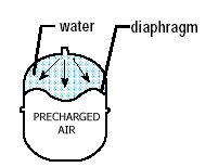
In Part 1 of this series, we looked at where thermal expansion tanks are needed. When it is determined that a tank should be included in the plumbing system, the next task is to select the correct tank size. Referring to sizing tables in an expansion tank manufacturer’s catalog is the easiest method, although not the best method, for sizing thermal expansion tanks. Sizing tables provided by the manufacturers give the tank model number and size based on the water heater’s volume and the system supply pressure. These tables, however, are based on three important assumptions that designers need to be aware of.
First, for most manufacturers, the tables are based on a maximum allowable line pressure of 150 psi. This is the maximum allowable working pressure of most water heaters and thermal expansion tanks. It is also the setting of the water heater relief valve. In other words, the thermal expansion tank, if selected by the tables, could accommodate the thermal expansion up to a system pressure of 150 psi, which is the relieving point for the water heater relief valve. Remember that the purpose of the thermal expansion tank is to prevent the relief valve from relieving. Sizing the thermal expansion tank for a maximum allowable pressure of 135 psi, which is 10% below the relief valve set point, is a better alternative.
[Read more…]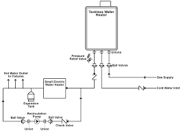
Thermal expansion tanks are typically installed in conjunction with storage water heaters, but are they needed with tankless water heaters? This issue can sometimes be overlooked. Let’s look at the specifics.
[Read more…]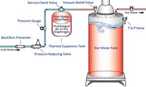
When are thermal expansion tanks needed and/or required in plumbing systems?
When heated, water expands. We know that. When the water heater heats water, it expands as much as possible. But what happens when a water heater heats water, and there is no subsequent hot water usage?
This can occur after a period of showering/bathing during peak times, followed by a period of no hot water usage. For example, hot water usage for showering in the evenings, followed by a period of no use while people sleep at night.
During peak usage, hot water stored in the water heater is distributed to end users, while cold water refills it. The cold water in the tank is heated, but when there is no subsequent hot water use, the heated water has no room to expand. If there is no place for the expanded water to go, the system pressure increases significantly. This leads to one of two possible scenarios:
[Read more…]
If you stay in this business long enough, you see a bit of everything. Notice the water heater’s T&P valve in the above photograph. The T&P valve discharges vertically upward. What’s wrong with that?
There are many specific code requirements (13 to be exact) for the discharge piping from water heater T&P valves (Ref: 2012 International Plumbing Code 504.6). This installation violates requirements 8 and 9, which are:
8. Not be trapped.
9. Be installed so as to flow by gravity.
Obviously, with this incorrect installation, the discharge cannot flow by gravity. Also, water can fill and remain in the discharge pipe. Over time, stagnant water in the discharge pipe can corrode it and cause it to fail.
The International Plumbing Code Section 504.6 contains 13 specific requirements for T&P relief valve discharge piping. Common violations beyond the upward discharge shown here include:
Each of these violations creates a potential safety hazard. When a T&P relief valve activates, scalding water or steam discharges through the pipe. Improper installation can direct that discharge toward occupants or into areas where it causes property damage.
This is just a reminder. During field inspections, check the discharge pipe to verify code compliance.
Suggest topics for future blog posts.