How To Size Thermal Expansion Tanks For Hot Water Systems – Part 2 of a 3-part series.
In Part 1 of this series, we looked at where thermal expansion tanks are needed. When it is determined that a tank should be included in the plumbing system, the next task is to select the correct tank size. Referring to sizing tables in an expansion tank manufacturer’s catalog is the easiest method, although not the best method, for sizing thermal expansion tanks. Sizing tables provided by the manufacturers give the tank model number and size based on the water heater’s volume and the system supply pressure. These tables, however, are based on three important assumptions that designers need to be aware of.
First, for most manufacturers, the tables are based on a maximum allowable line pressure of 150 psi. This is the maximum allowable working pressure of most water heaters and thermal expansion tanks. It is also the setting of the water heater relief valve. In other words, the thermal expansion tank, if selected by the tables, could accommodate the thermal expansion up to a system pressure of 150 psi, which is the relieving point for the water heater relief valve. Remember that the purpose of the thermal expansion tank is to prevent the relief valve from relieving. Sizing the thermal expansion tank for a maximum allowable pressure of 135 psi, which is 10% below the relief valve set point, is a better alternative.
Second, the manufacturer’s tables are based on a tank precharge pressure of 40 psi. Precharge is the air pressure on the airside of the tank bladder. This setting, by the way, is not based on an engineering principle but rather reflects the Department of Transportation’s limitation on transporting tanks. To reduce the size of the thermal expansion tank, the precharge air pressure should be set to the system line pressure, not the 40 psi factory-set precharge pressure. (Note: if expansion tanks are sized by an engineer based on a precharge air pressure equal to line pressure, the plumbing drawings and specifications should instruct the contractor to charge the expansion tank with air pressure equal to the line pressure.) Since the manufacturer’s sizing table is based on a tank precharge pressure of 40 psi, it does not accurately size an expansion tank when the precharge pressure equals the line pressure.
Third, most manufacturers’ sizing tables are based on a 400F temperature rise of the stored water. Think about this for a moment. The water heater is typically sized based on a 1000F temperature differential. For instance, we often assume that cold water enters the water heater at 400F and is heated to 1400F and stored. If we design the water heater to raise the water temperature to 1000F, a conservative approach is to size the thermal expansion tank to accommodate the water expansion resulting from that 1000F increase. This is, of course, a worst-case scenario (complete emptying of the tank and filling with 400F cold water). Designing the expansion tank based solely on a 400°F temperature rise is less than conservative.
To design a thermal expansion tank for a maximum allowable pressure less than 150 psi, a precharge air pressure different from 40 psi, and a temperature differential greater than 400F, we can’t consult the manufacturer’s tables. Also, on large systems, storage tank sizes are often larger than those given in the tables. So what do we do? We must calculate the proper expansion tank size using engineering equations. Here is a simplified method for sizing expansion tanks. A more detailed method is presented in the ASPE Design Handbook, Volume 4.
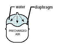
To select a thermal expansion tank, the total tank capacity and the acceptance volume must be determined. The total tank capacity is the volume of the tank. The acceptance volume is the amount of water the tank will accept when air pressure is applied to the air side of the diaphragm.
First, determine the water’s expansion volume in your system. This is the volume of water the expansion tank must accommodate, also called the “acceptance volume.” The volume of expanded water depends on the specific volume of water at the entering and heated temperatures and on the volume of stored water.
(1) VACC = VT x (Vs2/Vs1 – 1)
where,
VACC = Acceptance Volume (gallons)
Vs2 = Specific volume of water at heated temperature, (ft3/lb)
Vs1 = Specific volume of water at entering temperature, (ft3/lb)
VT = Water heater storage tank volume (gallons)
The specific volume of saturated water at various temperatures can be found in tables of thermodynamic properties or in the handy table in the ASPE Data Book, Volume 2, Table 6-5, Thermal Properties of Water. Here is a good number to remember. Water heated from 400F to 1400F will expand by 1.7%. For example, let’s assume we have a 120-gallon water heater and the water is heated from 400F to 1400F.
VACC = 120 (0.01629/0.01602 – 1) = 120 (.017) = 2.0 gallons
This is the amount of water that the thermal expansion tank would have to accept to prevent pressure spikes in the system. I know that this is a simplified approach. I have ignored the expansion of the heater tank and the hot water piping. In my experience, the impact of these factors is small and has little effect on the final tank selection.
Keep in mind that when we complete the calculations, we select expansion tanks that come in rather large size increments. That’s why factors that do not significantly affect the total thermal expansion required can be safely omitted from the calculations. If you want to be more precise, the equations in the ASPE Design Handbook account for pipe material expansion.
By the way, I also don’t bother correcting for altitude. We typically don’t need that much accuracy. Also, since we are assuming a 100-degree water temperature differential in the calculations, we have some built-in conservatism.
The final step is to determine the expansion tank’s total capacity. The equation for total expansion tank capacity is derived from Boyle’s law. When the precharge pressure equals the line pressure, use equation (2) below.
(2) VET = VACC / (1- P1/P2)
where,
P1 = Static water line pressure (psia)
P2 = Maximum desired tank pressure (psia)
VACC = Acceptance volume (gallons)
VET = Total volume of the expansion tank (gallons)
(Note that the pressures are absolute pressures (psia). Add 14.7 to the gauge pressure to convert to absolute pressure. Also, note that this equation assumes the air precharge pressure equals the line pressure. This equation should not be used if the precharge pressure does not equal the line pressure.)
If the expansion tank has a 150 psi allowable working pressure, I use 149.7 psia (135 + 14.7 = 149.7) for P2, which is 10% below the relief valve’s set point. Using our example above, let’s assume that the actual line pressure and precharge pressure are 80 psi.
VET = 2.0 / (1 – 94.7/149.7) = 5.44 gallons
Given a calculated total tank capacity of 5.44 gallons and an acceptance capacity of 2 gallons, consult the manufacturer’s data and select a tank that meets your specific application.
If the precharge pressure does not equal the line pressure, equation (2) cannot be used. The appropriate equation for a precharge pressure that does not equal the line pressure is equation 3 below.
(3) VET = VACC / [(P1/P2) – (P1/P3)]
where,
P1 = Precharge pressure (psia)
P2 = Static water line pressure (psia)
P3 = Maximum desired tank pressure (psia)
VACC = Acceptance volume (gallons)
VET = Total volume of the expansion tank (gallons)
For the preceding example, if the expansion tank has a factory precharge of 40 psig and it is not increased to the line pressure of 80 psig, then the required total capacity of the expansion tank increases from 5.4 gallons to 9.4 gallons.
Some manufacturer’s now also have sizing calculators based on these engineering equations on their websites. Click here for an example.
The sizing method described above is for thermal expansion tanks installed in a hot water system. If you are sizing tanks for a booster pump system, the procedure is different.
Part 2 of a 3-part series.
For suggestions on future blog posts, make a suggestion.
I have two storage tanks at 1128 gal each.
when I use 2256 in the equation I get expansion tank vol to be 105 gal, which seems wrong.
I Have 4 heaters at 25 gpm flow rate each 4 Circulating pumps.
Please advise