Roger W. Griffith, P.E.

  • Home
  • About Roger
  • Engineering
    • Plumbing
    • Hot Water Scalding
    • Carbon Monoxide Poisoning
    • Legionella
  • Expert Witness
  • Blog
  • Contact

ASSE 1016 Shower Valves

January 16, 2019 by Roger Griffith Leave a Comment

Showers pose a risk for hot water scalding.  In addition to the potential for hot water scalding, thermal shock from rapid changes in shower water temperature can cause slips and falls.

To protect the user, plumbing codes require water delivery from showers to not exceed 120 degrees F. Water heater thermostats are no longer considered a safe means for controlling water temperatures when the code requires a maximum water temperature at showers and tub/showers. The plumbing codes now require the installation of the American Society of Sanitary Engineers (ASSE)  1016 shower valves to prevent scalding and thermal shock.

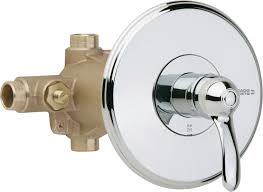
ASSE 1016 contains requirements for three different types of shower valves.

  • Type P: Pressure compensating. This is the most common type of shower valve.
  • Type T: Temperature compensating
  • Type P/T: Pressure and temperature compensating

Design engineers have to decide what type of ASSE 1016 shower valves to specify. First, for individual showers and tub/showers, a Type P pressure compensating valve is required to prevent thermal shock. Unless thermal shock protection is provided by another device, such as an ASSE 1066 pressure-compensating device, a Type P or Type P/T valve is required.

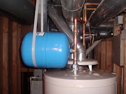
Second, the question becomes, is the additional thermostatic protection provided by a Type P/T shower valve needed? This often depends on the hot water system and the amount of temperature variation that can be expected at the shower fixture. Some hot water systems have large temperature variations, for example, residential storage-type water heaters with no recirculation. Due to the phenomenon of  “thermal stacking,” hot water temperatures in these systems can easily vary by as much as 10 – 15 degrees F. Another consideration is whether the facility has a higher risk for scalding, such as hospitals, nursing homes, and assisted living centers. In these instances, a Type P/T shower valve is a good idea.

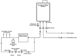
By contrast, some commercial hot water systems with master mixing valves, continuous recirculation, and/or precise controls may have nearly constant hot water temperatures at the shower fixtures. For these systems, a Type P shower valve may be sufficient to limit temperatures at the shower to a maximum of 120 degrees F.

Here is a conservative approach: if system temperatures are not stable or unknown, install a thermostatic device (ASSE 1017 master mixing valve in conjunction with ASSE 1016 Type P shower valves, ASSE Type P/T shower valves, etc.) at some point between the water heating source and the delivery point. Although this is not a code requirement, maintaining a maximum temperature of 120 degrees F is. A thermostatic device will greatly reduce temperature swings in the hot water system and also protect the end-user in case of a failure of the water heater thermostat.  Design engineers should evaluate the hot water system and make an informed decision about scald protection. Specifying what “everyone else does” or “what meets the code” may not provide the required level of safety needed to prevent scalding.

Given the allowable temperature variation in the ASSE 1016 standard, at what temperature should shower valves be set to ensure a maximum water temperature of 120 degrees F? Outlet temperatures for ASSE 1016 valves can vary by +/- 3.6 degrees when tested at 45 psi. At higher operating pressures, the temperature swing could be greater than the +/-3.6 degrees F. Therefore, I recommend the high-limit stops on shower valves be set to provide a discharge temperature of 110 degrees F. If a shower valve is set to 110 degrees F, the actual discharge temperature may vary from 105 to 115 degrees F. This temperature range provides a comfortable shower without the risks of hot water scalding.

Options: integral check stops:  Always specify shower valves with integral check stops to prevent the hot water from crossing over into the cold water piping.

Plumbing specifications should require high-limit stops to be set at the time of installation. The design engineer should also check the hot water temperatures during site inspections prior to project completion.


Filed Under: Hot Water Scalding, Hot Water Systems, International Plumbing Code, Plumbing Systems, Recent Posts Tagged With: Shower valves

Careful! The Wrong Showerhead May Scald You

January 7, 2019 by Roger Griffith Leave a Comment

Shower head

If not specified and installed correctly, showerheads can cause scalding!

Currently, standard shower valves and showerheads have a minimum flow rate of 2.5 GPM. There are water-saving shower valves and showerheads available with lower flow rates. WaterSense showerheads are rated at 2.0 GPM. There are also showerheads available that have 1.5, 1.0, and even 0.5 GPM flow rates. These various options for minimum flow rates in shower valves and showerheads create an opportunity for misapplication and dangerous results.

When the flow rate of a showerhead is less than the minimum flow rate of the corresponding shower valve, the potential for scalding increases for the following reasons: [Read more…]

Filed Under: Hot Water Scalding, Hot Water Systems, International Plumbing Code, Plumbing Systems Tagged With: Showerheads

Designing Plumbing Systems To Minimize Legionella

August 28, 2015 by Roger Griffith 2 Comments

legionella bacteria

The recent outbreak of legionnaires’ disease in New York City has brought renewed attention to the inherent risks from legionella bacteria in HVAC and plumbing systems. There are several things that plumbing engineers and designers can do to minimize the risk of legionella colonizing and growing in plumbing systems.

[Read more…]

Filed Under: Hot Water Systems, Legionella, Plumbing Systems

Thermal Expansion Tanks: Part 3

August 24, 2015 by Roger Griffith Leave a Comment

Selection and Installation of Thermal Expansion Tanks

thermal expansion tank support

See Part 2 for calculating the expansion tank volumes. Now, using the calculated acceptance volume and total volume for the tank, select an expansion tank from the manufacturer’s data that meets these requirements.

Be aware that in most states, unfired pressure vessels larger than a certain volume must have an ASME stamp. Check your state’s requirement for this limit. If the expansion tank you need is larger than this limitation, it must be constructed in accordance with ASME Section VIII requirements. ASME rated vessels are much higher in cost than non-ASME vessels. Installing multiple smaller tanks, which are below the volume limitation for ASME tanks, is also an option. Most tank manufacturers offer both ASME and non-ASME thermal expansion tanks.

[Read more…]

Filed Under: Hot Water Systems, Plumbing Systems, Water Heaters Tagged With: thermal expansion tanks

Thermal Expansion Tanks: Part 2 – Sizing

July 31, 2015 by Roger Griffith 1 Comment

How To Size Thermal Expansion Tanks For Hot Water Systems

thermal expansion tank

In Part 1 of this series, we looked at where thermal expansion tanks are needed. When it is determined that a tank should be included in the plumbing system, the next task is to determine the correct size for the tank. Referring to sizing tables in an expansion tank manufacturer’s catalog is the easiest method, although not the best method, for sizing thermal expansion tanks. Sizing tables provided by the manufacturers, give the tank model number and size based on the water heater’s volume and the system supply pressure. These tables, however, are based on three important assumptions that designers need to be aware of.

First, for most manufacturers, the tables are based on a maximum allowable line pressure of 150 psi. This is the maximum allowable working pressure of most water heaters and thermal expansion tanks. It is also the setting of the water heater relief valve. In other words, the thermal expansion tank, if selected by the tables, could accommodate the thermal expansion up to a system pressure of 150 psi, which is the relieving point for the water heater relief valve. Remember that the purpose of the thermal expansion tank is to avoid the relief valve from relieving. Sizing the thermal expansion tank for a maximum allowable pressure of 135 psi, which is 10% below the relief valve set point, is a better alternative.

[Read more…]

Filed Under: Hot Water Systems, Plumbing Systems, Water Heaters Tagged With: thermal expansion tanks

Are Thermal Expansion Tanks Needed With Tankless Water Heaters?

June 21, 2015 by Roger Griffith 15 Comments

tankless water heater schematic with hot water recirculation

Thermal expansion tanks are typically installed in conjunction with storage water heaters, but are they needed with tankless water heaters? This issue can sometimes be overlooked. Let’s look at the specifics. [Read more…]

Filed Under: Hot Water Systems, International Plumbing Code, Water Heaters Tagged With: thermal expansion tanks

Thermal Expansion Tanks: Part 1 – The Need

June 20, 2015 by Roger Griffith 5 Comments

thermal expansion tank with water heater

When are thermal expansion tanks needed and/or required in plumbing systems?

When heated, water expands. We know that. When water is heated in a water heater, the water expands, if possible. But what happens when water is heated in a water heater and there is no hot water usage?

This can occur after a period of showering/bathing during peak times followed by a period of no hot water usage. For example, evenings are a time when there is hot water usage for showering followed by a period of no usage while people are sleeping during the night.

During peak usage times, hot water stored in the water heater is distributed to the end-users, and cold water fills the water heater. The cold water in the tank is then heated, but when there is no subsequent hot water usage, the heated water has no room for expansion. If there is no place for the expanded water to go, the pressure in the system increases significantly. This leads to one of two possible scenarios:

[Read more…]

Filed Under: Hot Water Systems, International Plumbing Code, Plumbing Systems, Water Heaters Tagged With: thermal expansion tanks

What’s Wrong With This Picture?

September 18, 2014 by Roger Griffith Leave a Comment

Water Heater T&P relief valve discharge piping, installed incorrectly

If you stay in this business long enough, you see a bit of everything. Notice the water heater’s T&P valve in the above photograph. The T&P valve discharges vertically up. What’s wrong with that?

There are many specific code requirements (13 to be exact) for the discharge piping from water heater T&P valves (Ref: 2012 International Plumbing Code 504.6). This installation violates requirements 8 and 9, which are:

8.  Not be trapped.

9. Be installed so as to flow by gravity.

Obviously, with this incorrect installation, the discharge cannot flow by gravity. Also, water can fill and remain in the discharge pipe. Over time, stagnant water that remains in the discharge pipe can corrode the pipe and cause it to fail.

This is just a reminder. During field inspections, check the discharge pipe to verify code compliance.


For topics on future blog posts, make a suggestion.

Filed Under: Hot Water Systems, International Plumbing Code, Plumbing Systems, Water Heaters Tagged With: T&P relief valves

Contact Me

Roger W. Griffith, P.E.
(865) 471-8142
RGriffith@GriffithEngineering.net

Get all the latest content delivered to your inbox. (No spam; I promise)

See more content from Roger

[smbtoolbar]

Recent Posts

  • Flexible Air Ducts versus Flexible Air Connectors – What Is the Difference?
  • Correct Usage of Sanitary Tees in Plumbing Drains
  • Does the Plumbing Code Prohibit Trap Seal Devices?

Categories

  • HVAC Systems (6)
    • Carbon monoxide poisoning (1)
    • Gas appliances (1)
    • International Mechanical Code (3)
  • Plumbing Systems (13)
    • Hot Water Scalding (2)
    • Hot Water Systems (8)
    • International Fuel Gas Code (2)
    • International Plumbing Code (8)
    • Legionella (1)
    • Water Heaters (5)
  • Recent Posts (3)
  • Sprinkler Systems (2)

Roger W. Griffith, P.E.
P.O. Box 702
Jefferson City, TN 37760
(865) 471-8142

Email: rgriffith@griffithengineering.net

Site Links

  • Home
  • About Roger
  • Engineering
  • Expert Witness
  • Blog
  • Privacy Policy
  • Contact

What can we help you find?

See more content

[smbtoolbar]

Copyright © 2025 · Agency Pro Theme on Genesis Framework · WordPress · Log in